Path
Intelligent Object For 3D Rad
Use this object to make 3d virtual paths that other objects linked to it can follow.
The course is defined by specifying nodes (3d locations) as a list of coordinates. The resulting smooth curve which passes through all the points you have defined is automatically computed by using a spline algorithm.
Path location, orientation and scaling can be edited in the Virtual Editor.
The actual path is visualized in real-time while you edit the project.
This object can be used to move targets around in a shooter game, create reference courses for AI based vehicles and so on.
For details on how to use paths with specific objects like for example SkinMesh or RigidBody please see the documentation for those particular objects.
If this option is not checked, the path will be ignored (not followed) by objects linked to it. It will only operate after it is started by another object, like for example EventOnInput.
If this option is checked, the path will not work as usual, run-time. Instead it will record its location at regular intervals, adding the coordinates to the list in the Path Nodes box, on the property dialog.
This feature allows you to use any moving object in the project to edit a new path. For example, you can attach the Path object to a car, set the Path mode to 'recording', launch the project and drive the car around to set new path nodes.
The Freq parameter defines the frequency at which you want to record the path locations. Setting this factor to zero will disable automatic recording. You will still be able to record a node by pressing the [R] key though.
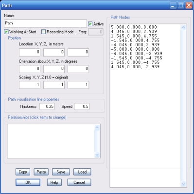
In this window you list the path nodes as a list of coordinates.
For each line of text, you must specify the X, Y and Z coordinates of the node, separated by a comma.
The values are in meters and they are relative to the current Path object's position.
Note that the first node will be the center of the Path object in the editor. It means that, if you want the node coordinates to be absolute (world-center-relative), Path object orientation must be zero, scaling must be 1 and location must match first node coordinates.
These two parameters allow you to set thickness (in meters) and speed (total time, in seconds, to complete a path loop) for the path visualization line.
This list defines how the Path object relates to the objects linked to it. The following relationship types are supported: